Jumbo Powerbank
Jumbo powerbank project
Repurposing an old 12-cell lithium ion battery pack from a discontinued e-vehicle project.
I wanted a powerbank that would be able to power my router so a 12-volt output was needed. I also added two 3.1A USB charging ports and a 7-segment voltage readout.
The final specs were:
- One 12V 10A output
- Two 5.1V 3.1A USB charging ports
- 50 Watt charging (approx. 0.3c) from 12-20V
- Cooling fan auto-on when charging with manual override
Design
I started by designing an overall schematic of the powerbank. Initially, I wanted to use as much off the shelf components as I could, but I couldn’t find a battery balancing circuit that met my requirements. So I designed my own.
Battery balancing
 In order to implement balancing, I designed a voltage clamp based around a TL431 voltage reference IC. When the battery terminal voltage exceeds 4.1V, the BC327P transistor conducts and dumps the energy into an LED. I assumed that any imbalance would be mostly towards the end of the charge cycle so the current wouldn’t be too high.
The dump LEDs also function as the charge indicator lights on the front panel. As the battery charges, the LEDs will start to light up one at a time to indicate that particular cell is full.
Additionally, the balancing circuit is connected to the cells through a relay which only turns on while the pack is charging. This eliminates any quiescent current allowing the pack to stay fully charged for years.
Charging trigger
 I wanted the powerbank to only charge when the charge voltage was high enough. If the voltage was too low, the cables might burn out because of the required current to charge at 50 watts.
I used a 9.1V zener diode plus a generic diode for slightly higher voltage (they didn’t have a 10V zener in stock). When the input voltage increases higher than about 10.5V, the NPN transistor starts to conduct. This causes the BC327 to supply current to the 7805 voltage regulator which triggers the charging relays, balancing relays, and cooling fan.
Overall schematic

Construction
The cells
 I started with 12 Panasonic NCR18650B cells. They were spot welded in parallel so I had to clip the nickel strips to reconfigure them. One of the cells had a damaged wrapper so I re-wrapped it.
 I didn’t have access to a spot welder anymore so I had to solder the cells together. To make sure that I didn’t overheat them I used a very good soldering iron with a new tip and lots of flux. Then I made sure that the joint was fully cooled before soldering the next one.
Acquiring the parts
Most of the parts were ordered online from shopee and RS, some were from e-Gizmo and Alexan.


Assembling the powerbank
The assembly was fairly straightforward since I had already planned out the schematic. All that was left was to plan how the front panel would look.
 I first cut out the cooling fan and charging holes with a rotary tool. To do this I had to make a stencil on paper first, then taped it onto the case as a template.
The charging sockets just clicked into place and screwed in using self-tapping screws. I messed up and stripped the threads on one of them so I had to glue an extra layer of plastic behind the front panel to give the screw some extra bite.
 After soldering the components, I did a quick test-charge from the bench power supply before installing the batteries.
 Here’s a close-up look of the inside. The 7805 regulator for the charging trigger heated up more than expected and I didn’t have enough space to mount a normal heatsink, so I made a custom heatsink from copper sheets.
 After checking that all the circuits are working properly, I installed the batteries. To secure them, I used some plastic strapping for crates, and a layer of nonslip rubber to protect against sharp edges and to prevent slipping.
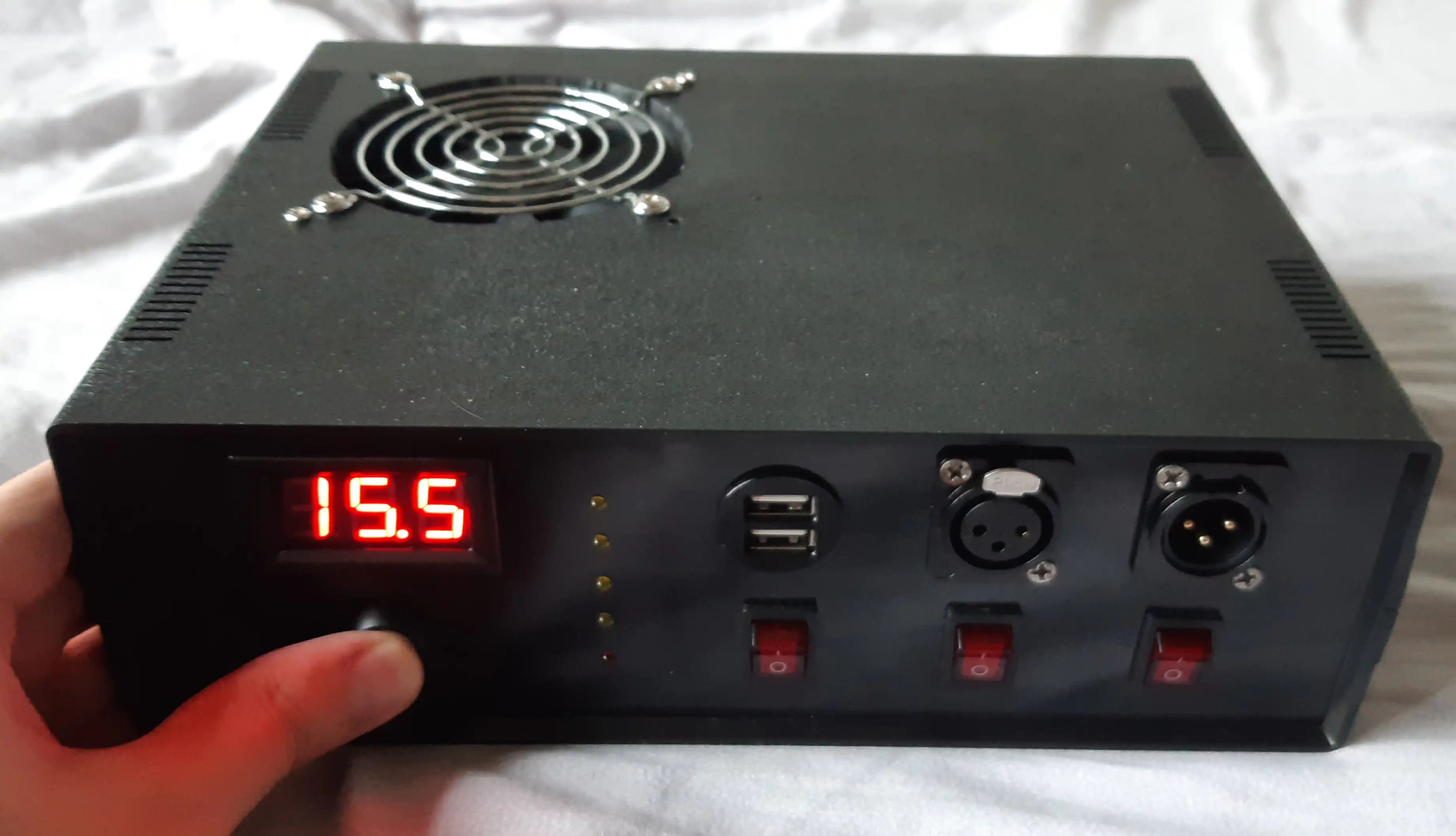
Done!

Testing the car charger

Next time I’ll make a custom PCB for the BMS and all the DC-DC converters to make it more compact. Ideally with synchronous switching it would be efficient enough to not need a cooling fan.